Register ready signals in low latency, zero bubble pipeline
Introduction
It’s that time of year at ITDev when we reflect on having said 'goodbye' to our interns from last year and 'hello' to our new graduates. As part of the onboarding of our graduates we provide guidance, coaching, training and, as for all our engineers, design reviews. This helps to avoid bad habits and further develops skills gained in education or from work experience. However, over the years we have found some embedded misunderstandings that can be very persistent; one of these is around pipelined systems.
Most graduates are aware of what a pipelined system should do, but misunderstandings about how the handshaking protocol works seems to lead to either loss of data or long latency; attempts to remedy this can lead to increasingly elaborate and confusing implementations. This blog will attempt to outline some straightforward implementations of pipe stages in VHDL, with examples demonstrating a simple AXI Streaming interface tested using a VUnit testbench. More information about VUnit can be found here; all code described in this blog is available for download from here.
AXI protocol and pipelining
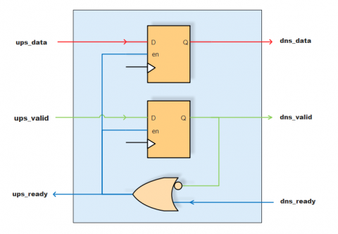
The building blocks of an AXI stream are pipe stages, the simplest of which consists of just 3 signals: valid, ready and data. A single cycle data transfer over an AXI interface involves an upstream entity asserting valid and data on the AXI interface, and a downstream entity accepting the data while driving a ready signal back upstream to confirm that the data can be accepted. If both valid and ready are asserted at the same time then the data ‘flows’ downstream.
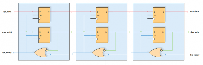
Figure 1: Axi pipe stages
Test infrastructure
The testbench consists of an AXI pipe stage, and the same stage modified to allow a registered ready signal. The two modules are daisy-chained together, with master and slave drivers providing and accepting stimulus data respectively. A ramp function is driven into the input interface of the first stage, the output data is verified in a simple process on the output interface of the second stage. The blocks shown in red are VUnit verification components which will drive the interfaces while conforming to AXI protocol.
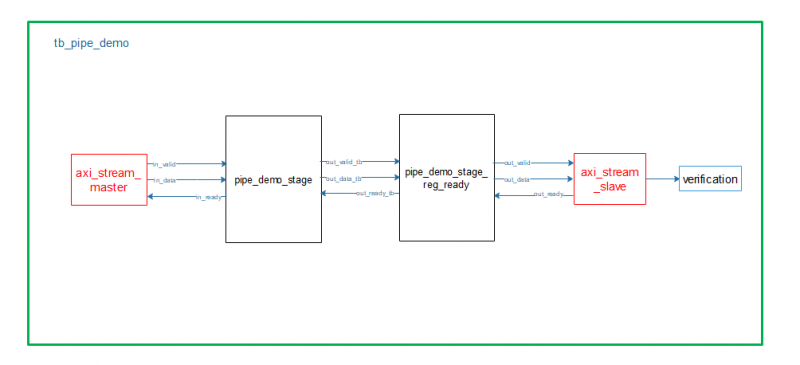
Figure 2: AXI pipe stage demonstration
Note: Information on installing and using VUnit can be found at https://vunit.github.io. The run.py script compiles the libraries needed for running the testbench and runs the tests.
Simple registered pipe stage
We can describe a simple register stage in this pipeline with valid and data registers gated by a ready signal. For power saving it is sometimes desirable to gate the data register based on the valid, but this will be left off in this demonstration for clarity.
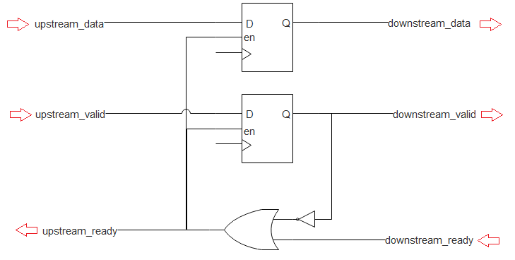
Figure 3: simple register stage (assume both registers are driven by the same clock)
The registers in this block are able to take in new data if either the downstream_ready is high (the data in these registers is being accepted downstream) OR downstream_valid is low (the registers currently have no valid data). Otherwise the register values are held constant until such time that the downstream ready asserts ‘1’ and we can resume flow.
We end up with the following implementation in RTL:
entity pipe_demo_stage is
port(
    clk      : in std_logic;

    -- upstream interface
    us_valid : in std_logic;
    us_data  : in std_logic_vector(7 downto 0);
    us_ready : out std_logic;

    -- downstream interface
    ds_valid : out std_logic := '0';
    ds_data  : out std_logic_vector(7 downto 0);
    ds_ready : in  std_logic
  );
end pipe_demo_stage;

architecture rtl of pipe_demo_stage is
begin

    process(clk) is
    begin
        if rising_edge(clk) then

            --accept data if ready is high
            if us_ready = '1' then
                ds_valid    <= us_valid;
                ds_data     <= us_data;
            end if;

        end if;
    end process;

    --ready signal with registered ready or primary data register is not valid
    us_ready <= ds_ready or not ds_valid;

end rtl;
A clocked process populating the output registers if the ready signal is high and a combinatorial assignment of the upstream ready signal. These stages can be stuck end to end to form a pipeline, presumably with some sort of processing happening in each block. For simplicity an FPGA-style Power on Reset value of ‘0’ has been used for ds_valid but a traditional reset can be used instead.
We can see in simulation that the valid and data signals are registered, and if the downstream is not ready, the upstream ready is de-asserted and data flow stops. When the downstream ready is re-asserted the flow resumes once more.
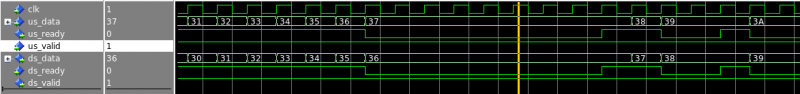
In the waves here the ready signal differs from the valid/data in that the ready signal is never registered, it must be passed upstream without delay to avoid overwriting the registered data. This can present a problem with timing closure, as it is possible to end up with a very long ready path routed through multiple pipe stages. In this case we can break up the ready path by registering the ready signal.
Pipe stage with registered ready signal
Registering the ready signal introduces a delay in the ready signal to the upstream stage. In this case the downstream ready is de-asserted, but since the upstream stage is using the registered signal it proceeds with driving data onto the interface for an extra cycle and the registered data is overwritten. The solution is to create a parallel set of registers into which the currently registered data can overflow if the downstream ready is de-asserted, while accepting the upstream data on the same cycle. If we see the downstream ready signal drop, we allow the currently registered data to flow into the expansion registers, while registering the incoming data from the upstream interface. When the downstream ready asserts we can drive the output from the expansion registers and resume normal flow on the next cycle. In this case the upstream ready signal is based on the availability of the expansion registers. The diagram below shows the basic principle:
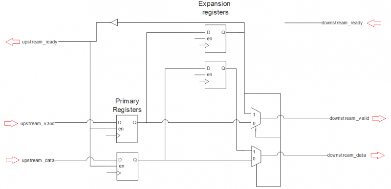
Figure 4: Pipe stage with registered ready
The diagram is missing a few things to preserve clarity - we must set the expansion valid register to zero after it is used to drive the output, and after adding the correct enable logic onto the expansion registers, we arrive at the following implementation in RTL:
entity pipe_demo_stage_reg_ready is
port(
    clk      : in std_logic;

    -- upstream interface
    us_valid : in std_logic;
    us_data  : in std_logic_vector(7 downto 0);
    us_ready : out std_logic;

    -- downstream interface
    ds_valid : out std_logic := '0';
    ds_data  : out std_logic_vector(7 downto 0);
    ds_ready : in  std_logic
  );
end pipe_demo_stage_reg_ready;

architecture rtl of pipe_demo_stage_reg_ready is

    -- expansion registers
    signal expansion_data_reg    : std_logic_vector(7 downto 0);
    signal expansion_valid_reg   : std_logic := '0';

    -- standard registers
    signal primary_data_reg      : std_logic_vector(7 downto 0);
    signal primary_valid_reg     : std_logic := '0';

begin

    process(clk) is
    begin
        if rising_edge(clk) then

            --accept data if ready is high
            if us_ready = '1' then
                primary_valid_reg    <= us_valid;
                primary_data_reg     <= us_data;
                -- when ds is not ready, accept data into expansion reg until it is valid
                if ds_ready = '0' then
                    expansion_valid_reg  <= primary_valid_reg;
                    expansion_data_reg   <= primary_data_reg;
                end if;
            end if;

            -- when ds becomes ready the expansion reg data is accepted and we must clear the valid register
            if ds_ready = '1' then
                expansion_valid_reg  <= '0';
            end if;

        end if;
    end process;

    --ready as long as there is nothing in the expansion register
    us_ready <= not expansion_valid_reg;

    --selecting the expansion register if it has valid data
    ds_valid <= expansion_valid_reg or primary_valid_reg;
    ds_data  <= expansion_data_reg when expansion_valid_reg else primary_data_reg;
end rtl;
The expansion registers are populated from the primary registers in the event of the upstream being ready and the downstream not being ready. The registers driving the downstream interface are selected based on whether there is valid data in the expansion register.
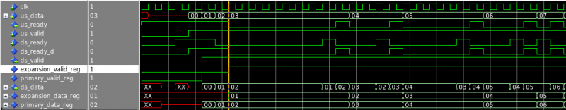
In simulation we see the expansion register being populated on the falling edge of the upstream ready, and then being used to drive the downstream interface on the rising edge of the same signal. Registering this ready signal allows us to break up the ready path, putting less pressure on routing for the ready signal.
Conclusion
We have shown here that if we understand and obey the rules of the AXI protocol then we can achieve low latency, bubble free pipeline implementations with minimal issues. We have also shown that registering the ready signal requires a little more thought, but it is not too painful if we understand why registering the ready signal can cause the pipeline to ‘overflow’. My advice to graduates approaching AXI protocol and pipelined systems for the first time is to start with the following line from the first implementation:
us_ready <= ds_ready or not ds_valid;
How ITDev Can Help
At ITDev we enjoy supporting good engineering practice. Aligned with this we run workshops to help develop industry best practices through collaborative sharing and learning.
We have a team of highly skilled engineers with a multi-disciplinary background, providing technology consultancy and hardware & software design services. Initial discussions are always free of charge, so if you have any questions, or would like to find out more, we would be delighted to speak to you. Email us or call us on +44 (0)23 8098 8890.