Raspberry Pi: The first steps to rapid development
So you’ve got a project that needs both low and high-level interfacing. Perhaps it requires the use of multiple sensors or inputs to determine an output or reaction.
Initial thoughts might send you towards some of the wonderful low-level development platforms, such as Mbed or Arduino devices (and they really are wonderful), but then you realise that your project also requires some higher-level interfacing such as network connectivity, database access or a web front-end.
Suddenly these low-level options seem a little more daunting with additional hardware needed or having to search through technical specifications to find the most appropriate board as an extra requirement. Even with familiarity of these development boards, the set-up time with networking is an overhead that you could most certainly do without.
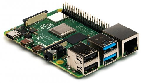
Your mind turns to the Raspberry Pi. By now, pretty much the world and his dog have heard of it and its success. You see that yes, it can perform low-level tasks such as toggling GPIO lines or communicating via SPI or I2C, and yes, it has onboard Ethernet1 (and in some cases WiFi and Bluetooth) and on top of all that, it runs a Linux distribution with full access to all of the aforementioned goodies.
Now that all sounds great, but perhaps you or your team have no experience with the Raspberry Pi and don’t know where to begin? That’s where this blog post comes in!
What will you get out of this?
This blog will cover some very fundamental first steps to open the eyes of those new to the world of Raspberry Pi, allowing you to see first-hand that some simple interfacing that you would expect from a low-level board can be quickly achieved with a Raspberry Pi. This will include toggling some GPIO lines with (where available) some LEDs.
Yes, I know this is simple, but these are first steps and once you have some reassurance of how easy it can be, there are many fantastic blogs and tutorials out there to help guide you the rest of the way.
In addition to this, there’s a github repository that provides some software referred to in this blog post. Feel free to make a clone of this and have a look through.
Also, well worth noting that there are many ways to carry out some of these tasks and many different tools that can be used to achieve the same goals. However, I have stuck to methods and tools that I use for simplicity, as I believe they should be accessible to most.
What you will need
For this blog post, it’s assumed that most of these things you’ll have around the lab in most engineering facilities. If not, there are plenty of useful kits around, for example this kit available from the PiHut.
Hardware
- A Windows PC2
- A Raspberry Pi with Ethernet or WiFi capability (in this blog I used a model 3B+)
- A USB power supply and Micro USB cable
- A MicroSD card
- A MicroSD card reader
- USB keyboard
- Monitor with HDMI input
- HDMI cable
- An Ethernet cable (where not using WiFi)
- A network with access to the internet
Additional components if toggling some LEDs
- A breadboard
- Tri-colour LED or selection of LEDs (I went with a board mounted LED for ease)
- A resistor (or resistors if using multiple LEDs)
- Dupont jumper cables (male to female)
Software (Windows)
Setting up the hardware
First, let’s get the Raspberry Pi hardware set up. This should be straight-forward, like setting up a standard PC (only significantly smaller). Connect the keyboard, monitor, Ethernet1 cable (where available), but leave the USB power and MicroSD card for a moment.
Now, download the latest Raspbian distribution. I went with the “Lite” version; it’s smaller and for this blog I won’t be using the Raspbian desktop, just the terminal and SSH interface, but by all means, give the other versions a spin.
Extract the image file and connect the card reader with MicroSD card to the PC. Open Win32DiskImager (it has a fairly simple interface) and carefully select the correct drive and the extracted image file using the drop-down menu and browse button respectively. Once you’re happy with this, click “Write” and wait for the “Write Successful” pop-up. Depending on the size and speed rating of your card, this should only take a minute or two.
Once this is complete, take the MicroSD card out of the reader and fit it into the Raspberry Pi, plug in the power from the USB supply and away we go! You should now see the Raspberry Pi boot sequence appear on the monitor.
Setting up the Raspberry Pi for initial use
One thing you may notice, and as my colleague, Simon, points out in his blog, a great deal of the software requirements on the Raspberry Pi are either already installed, or can be obtained quickly using the apt or apt-get command. Additionally, unlike a lot of other embedded platforms, the Raspberry Pi has a wealth of libraries either included or easily accessible. This makes creating applications easier and saves time having to re-write drivers and low-level code on a per-project basis.
The first thing you’ll want to know is the log-in details. The default user is 'pi', with the password 'raspberry'. Log in with these credentials, and let’s get installing (make sure your Pi has access to the internet).
Updating
The image we’ve just installed might not quite have all the latest updates to all software packages, so let’s make sure we’re running with the very latest and greatest software packages.
pi@raspberrypi:~ $ sudo apt update && sudo apt upgrade
This will update all of the applications already installed.
Remote access (optional, but used in this blog post)
If you’d rather work directly on the Raspberry Pi, please feel free to skip the following section and parts involving WinSCP or connecting via PuTTY. The Raspberry Pi comes with both nano and vi installed, should you wish to use these command line editors instead.
The Raspberry Pi comes with all you need to remotely connect to it (in headless mode), however it needs to be enabled. Let’s get that and another other useful feature enabled now.
pi@raspberrypi:~ $ sudo raspi-config
Running this command will launch the Raspberry Pi configuration UI, from which you can navigate using the arrow keys. Navigate to “Interfacing Options”. Within here, there are two options that need to be updated: “SSH” and “Remote GPIO”. Go ahead and turn both of these on.

From here, we need to find out the IP address so that we can connect to it remotely. You can skip this section if you’re happy to work directly on the Raspberry Pi.
Run ifconfig and obtain the IP address.
pi@raspberrypi:~ $ ifconfig

Now, try connecting to the Raspberry Pi remotely using PuTTY. The default settings on PuTTY should suffice, just add “pi@” followed by the IP address, e.g. pi@192.168.23.143 and then click “Open”. It should give you a credential warning, which you can check then proceed.
You will then be prompted for the password for the user pi. Enter the password and voilà, you’re now able to operate the Raspberry Pi from your remote PC. At this point, you can disconnect the keyboard and monitor from the Raspberry Pi, as you won’t need it for the remainder of this blog post.
Toggling GPIOs
We now want to be able to modify the GPIO lines so that we can turn an LED, or LEDs on and off. To do so, we’ll need a little bit of additional software.
wiringPi
pi@raspberrypi:~ $ sudo apt install wiringpi
wiringPi provides C and C++ libraries, as well as some useful applications. You can also install wiringPi libraries for Python.
Go ahead and run the command above then try the following:
pi@raspberrypi:~ $ gpio readall

Well isn’t that lovely? This gives you a very quick way of viewing the current state of every pin on the Raspberry Pi, including power, GPIOs, serial, SPI etc. Neat, eh? It’s also pretty useful to help negotiate one of the gotchas that users often encounter (pins can have three identifying values: board, BCM or GPIO). For the purposes of this blog, I will differentiate by referring to physical pins in the board as pin X, GPIOs in software as GPIO Y, and not using the BCM number in any description.
Whilst this gives a very nice overview of all pins on the Raspberry Pi, it is a little clustered. If we just want to read the digital value at pin 11 (GPIO 0), we can use:
pi@raspberrypi:~ $ gpio read 0
This will give a result of 0 or 1 (where 1 implies the voltage at the pin is 3.3V), showing us the output level on that GPIO without having to probe it.
From here, we can now hook up an LED. Whilst this is optional, it does make for a fun test. I hooked up a board mounted common cathode RGB LED with the pins as follows:
- Pin 11 (GPIO 0) to the red anode
- Pin 12 (GPIO 1) to the green anode
- Pin 13 (GPIO 2) to the blue anode
- Pin 14 (0V) to the common cathode
Note: This LED board has built-in resistors, you will need some protective resistors if using discrete LEDs instead. For most LEDs, 330Ω resistor is generally a good choice, but please find an appropriate value for your LED(s) of choice, given the input voltage from the Raspberry Pi’s GPIO is 3.3V.
So, now we have the LED or LEDs hooked up, let’s switch it on. Using the gpio application, we need to firstly set the mode of the GPIO, then the output level.
If we run the following with the RGB LED set up as above, we should see the LED glow red:
pi@raspberrypi:~ $ gpio mode 0 out
pi@raspberrypi:~ $ gpio write 0 1
And following on from this, we can repeat the command, swapping out the red GPIO line (0) for the green and blue (1 and 2 respectively). Go ahead and update those. The RGB LED should now be glowing white (or thereabouts without being able to adjust the brightness of the LEDs). To turn off one of these LEDs, write a zero to the GPIO:
pi@raspberrypi:~ $ gpio write 0 0
Providing all that worked, we can now turn the individual colours on and off using the gpio application. Have a play around. Without Pulse Width Modulation3 (PWM) you’ll only be able to achieve solid colours, but it’s still a start.
One pitfall is that the pins/GPIOs can be labelled in one of three ways:
- Board pin – The physical pin on the Raspberry Pi
- BCM - The Broadcom SOC channel
- wiringPi – The wiringPi software GPIO number
The differences can be confusing, but once you have your head around it, it becomes a little easier to map between them, and by running gpio readall on the command line, you will quickly get a visual reminder of how they all map together.
Updating GPIOs programmatically
Being able to toggle the GPIOs is great, but what we really want is a little more automation. We could create some simple aliases that set the GPIO values using gpio write calls but where’s the fun in that? Let’s write a simple C application using our PC’s editor and WinSCP.
Edit in Windows, build on the Raspberry Pi
If you’re working directly on the Raspberry Pi, feel free to launch your editor of choice, otherwise launch WinSCP. You’ll be met with a login window, similar to that of PuTTY.
- Enter the Raspberry Pi’s IP address into the host name field,
- Set the username to pi
- Click 'Login'
- Check the credential message and accept
- Enter the password and click 'OK'
You should now see the window with your local files on the left and the home directory of the pi user on the right. Feel free to change these directories to somewhere more convenient than the default location picked by WinSCP.
If you want the changes that you make on your local machine to be immediately reflected on the Raspberry Pi, select “Commands” > “Keep remote directory up to date…” (keyboard shortcut: Ctrl + U, or icon with the red and green arrows), otherwise you can manually copy the files over, or use the “Synchronize” command. I will be automatically copying files over as and when they change.
In your PuTTY terminal, navigate to the directory you have chosen WinSCP to write your files to on the Raspberry Pi before continuing.
GPIO control in C/C++
The Raspbian distribution comes with gcc and g++ already installed, so writing a very quick C or C++ application can be achieved in minutes. Whilst I have included a sample C application with makefile in the git repository, let’s write something quick from scratch.
Create a new file in your local synchronized directory and edit using an editor of your choice. I called my file led_select.c.
Copy in the source code below into your text editor:
#include <wiringpi.h>
#include <string.h>
#include <stdio.h>
#include <stdlib.h>

/* GPIO mappings for LED pins */
typedef enum LedMapping
{
    RED_GPIO = 0,
    GRN_GPIO = 1,
    BLU_GPIO = 2,
    LED_COUNT
} LedMapping_t;

/* Main entry point */
int main(int argc, char **argv)
{
    /* WiringPi set up */
    wiringPiSetup();
    pinMode(RED_GPIO, OUTPUT);
    pinMode(GRN_GPIO, OUTPUT);
    pinMode(BLU_GPIO, OUTPUT);

    /* Check input arguments */
    int gpio = -1;
    if (argc >= 2)
    {
        if (strcmp(argv[1], "red") == 0)
        {
            printf("Turning the red LED on.\n");
            gpio = RED_GPIO;
        }
        else if (strcmp(argv[1], "green") == 0)
        {
            printf("Turning the green LED on.\n");
            gpio = GRN_GPIO;
        }
        else if (strcmp(argv[1], "blue") == 0)
        {
            printf("Turning the blue LED on.\n");
            gpio = BLU_GPIO;
        }
    }
    else
    {
        printf("Usage: ./%s <colour> {red|green|blue}\n", __FILE__);
    }

    /* Loop through available LEDs and turn on relevant GPIOs */
    static const int AVAILABLE_GPIOS[LED_COUNT] =
    {
        RED_GPIO,
        GRN_GPIO,
        BLU_GPIO
    };
    for (int i = 0; i < LED_COUNT; ++i)
    {
        digitalWrite(AVAILABLE_GPIOS[i], AVAILABLE_GPIOS[i] == gpio);
    }
    return EXIT_SUCCESS;
}
Compile by entering the following into your PuTTY terminal:
pi@raspberrypi:~ $ gcc led_select.c -o led_select -lwiringPi
Noting that the wiringPi library is required for linking, and make sure the name of your C file matches.
The application must be called with super user permissions, e.g. run with sudo prefix:
pi@raspberrypi:~ $ sudo ./led_select <colour>
Here’s a quick breakdown of the important functions in this application:
wiringPiSetup()
This function initialises wiringPi and checks for certain requirements, such as super user support.
pinMode(pin, mode)
This function tells wiringPi what mode you want the pin to be in. In this case, we want to be able to write to all three pins, so this function is called three times with the matching GPIO values, using the defined OUTPUT value to indicate the mode.
digitalWrite(pin, value)
This function sets the state of the GPIO. The value is either HIGH or LOW, which translates to integers 1 or 0.
The rest…
The rest of the source is merely there to handle the input argument from the user. It will take in and process one colour string argument, i.e. if you call
./led_select green
, the green LED will be illuminated, while red and blue will be turned off. Passing in anything else, including no argument at all, will turn off all LEDs.
This should now (hopefully) build and run on your Raspberry Pi via the PuTTY terminal, allowing you to pick one of the LED colours, or at least toggle the GPIO lines. If it does not work as expected, we’ll spend a brief bit of time debugging the application, which will hopefully identify any issues that might have arisen.
Whilst this isn’t the most thorough or well-rounded application, it does give you a very quick glimpse of how quickly we can get started with a Raspberry Pi, manipulating GPIO lines.
Debugging
So, with any luck, the code provided has compiled and the LED should be changing as expected. If not, let’s run through one or two things that could’ve gone wrong.
Linking problems
If you happen to see a linker error such as “undefined reference to `wiringPiSetup'”, please ensure that you’re correctly linking the wiringPi library using
-lwiringPi
, noting that it is case sensitive!
Hardware
Firstly, the code uses GPIOs 0, 1 and 2. These map to pins 11, 12 and 13 respectively. I also connected pin 14 (ground) to the common cathode on the RGB LED (assuming you’re using the same or similar). Check that these are connected to the LED as expected using a multimeter. Bear in mind that the Raspberry Pi drives GPIO lines at 3.3V, so make sure that the LED can be driven from this voltage with their respective resistors.
GPIOs
Following this, if the connectivity looks good but we still have no action on the LEDs, let’s check that the GPIO lines are toggling as expected.
By running gpio readall, we should see that pins 11, 12 and 13 are set to mode “OUT”. If not, check that you have firstly run the wiringPiSetup() function, and that you have correctly set the mode for each GPIO to the defined value OUTPUT, which maps to value 1.
Run your application again and check that the modes are now correct.
Outputs and argument parsing
At this point, it may be down to a typing error or case mismatches between the arguments provided and the strings they are being checked against. The sample application is a little basic, so the only input argument being checked is the first one after the application name, and it assumes it will be written in all lower case.
If you aren’t seeing any messages printed to the screen, there’s a good chance the logic isn’t seeing your input argument properly. Feel free to add a line such as the one below inside the for-loop, where digitalWrite() is called:
printf("Setting GPIO %s\n”, (AVAILABLE_GPIOS[i] == gpio) ? “high” : “low”);That will then display the value of each GPIO line. If they’re all being turned off, it’s a good indication that the logic isn’t quite right.
By now, hopefully any issues have been resolved. If not, the Raspberry Pi should come with gdb installed, which can be a vital tool when debugging on the command line.
Overview
In a relatively short period of time (I would hope), we’ve gone from a Raspberry Pi with a handful of components, to an automated flashing light that can be controlled using an application written using a Windows development machine.
Once again, this is one of the simplest things that can be done, but it should hopefully provide you with enough hands-on experience with the Raspberry Pi and the accompanying software to begin to appreciate its simplicity, and with any luck, the confidence to consider using the Raspberry Pi for more of your projects.
Where to go from here?
If you haven't already visited the Github repository mentioned in the 'What will you get out of this' paragraph above, it's worth taking a look. This repository accompanies this blog and contains all the software mentioned, another example file as well as a readme which explains in detail how to go about using how to go about using the contents of the repository.
The Raspberry Pi foundation has some great blogs, tutorials, forums and information to get most people started, along with their official magazine, the MagPi.
The Raspberry Pi subreddit, (with over 1.5 million subscribers at the time of writing) where users post questions, projects and a lot of interesting material.
How ITDev Can Help
As a provider of software and electronics design services, we have extensive experience in building, modifying and debugging embedded software.
We are experienced in choosing the right platform for our client's development needs, ensuring they can achieve their goals with the right trade-off between time, cost and quality. We consider the suitability of off-the-shelf development platforms, especially when getting prototypes or proof-of-concepts quickly developed. These have the benefits of large development communities and support libraries.
In line with our use of open source libraries and materials, we enjoy contributing back to the engineering community, helping to develop engineering best practice. We do this by running our own events aimed at industry professionals.
We are always happy to offer advice and assistance to companies, so if you have a need and are unsure what approach to take, get in contact. Our initial consultation is free.
To arrange an initial consultation email us or call us on +44 (0)23 8098 8890.
 Footnotes
1 Ethernet is available (in a variety of speeds) on all standard models, not the Zero. See this informative chart that indicates some of the more important model information. For more in depth information, this chart contains almost everything else you might need to know.
2 The initial set up and communications are going to be carried out using a Windows machine, rather than a Linux or Mac.
3 Pulse Width Modulation (PWM) tutorial
Main image: www.commons.wikimedia.org